

Description
Overview
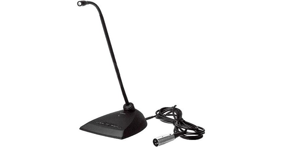
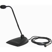
Shure Microflex® MX400D Series microphones are miniature electret condenser gooseneck microphones with a desktop base and a 4.3 m (14 ft.) cable. Desktop base allows microphones to be used in multi-purpose rooms where quick setup is required, or where permanent installation is impractical.
- Wide dynamic range and frequency response for accurate sound reproduction
- Interchangeable cartridges that provide a choice of polar pattern for each application
- Programmable mute button and LED indicator
- Logic input and output terminals for remote control or use with automatic microphone mixers
- Balanced, transformerless output for increased immunity to noise over long cable runs
- RF filtering
Interchangeable Cartridges
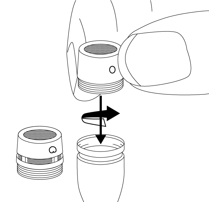
Microflex microphones use interchangeable cartridges that allow you to choose the polar pattern for different installations.


Snap-Fit Windscreen
- Snap into the groove below the cartridge.
- To remove, spread the gap with a screwdriver or thumbnail.
- Provides 30 dB of “pop” protection.

Microphone Placement
- Aim the microphone toward the desired source, such as the talker.
- Aim it away from any unwanted source, such as a loudspeaker.
- Place the tip of the microphone within 15 to 30 cm (6 to 12 inches) of the desired sound source.
- Always use the supplied windscreen or optional metal windscreen to control breath noise.
- If four or more microphones will be open at the same time, use of an automatic mixer is recommended.
Securing to a Surface

Drill two holes in the mounting surface 50.8 mm (2 in.) apart.
Use #6-32 screws to secure the microphone.
DIP Switches
Use the DIP switches to configure logic settings and mute button behavior.
The DIP switches are covered with a piece of clear tape at the factory. Remove tape to modify the switch settings.
Note: Bottom cover must be closed for microphone to function.

| OFF (factory default) | ON | |
|---|---|---|
| 1 | Momentary | Toggle |
| 2 | Push-to-mute | Push-to-talk |
| 3 | Mute button enabled, LED illuminates when mic is active | Disable mute button (microphone always on), logic controls LED |
| 4 | — | — |
Wiring Diagram
NOTE: Audio and logic ground are connected at microphone base.

Changing SWITCH OUT to Always Momentary
Use the following modification in situations where your logic interface requires momentary closure of the SWITCH OUT, but you want the mute button to toggle the microphone (DIP switch 1 ON, 3 OFF):
- Access the circuit board inside the microphone base.
- Remove the resistor at R45 and reinstall it at location R46.

Mute Button Configuration
Use DIP switches 1 and 2 to configure the mute button, as follows.
Be sure to set DIP switch 3 off (factory default) so that the mute button controls audio from the microphone.
| Switch Function | DIP Switch Setting |
|---|---|
| Momentary: push-to-mute (as shipped). |  |
| Momentary: push-to-talk |  |
| Toggle: (Push On/Push Off): Mic is active when powered on |  |
| Toggle: (Push On/Push Off): Mic is mute when powered on |  |
Connecting to an Automatic Mixer
Use these settings if connecting the microphone to an automatic mixer or other device that mutes audio and controls the LED.
- Connect logic leads to the automatic mixer. Connect the LED IN to the gate output to illuminate the LED when that channel is gated on.
- Set DIP switch 3 on. This disbles the mute button (the microphone passes audio regardless of whether the button is pressed or not).
- Set DIP switch 1 to configure how the mute button sends SWITCH OUT logic:

Momentary: push = 0 Vdc, release = 5 Vdc

Toggle: initial = 5 Vdc, push = 0 Vdc
Logic Wiring

Green (LOGIC GROUND): Connects to the logic ground of an automatic mixer, switcher, or other equipment.
Orange (LED IN): Set DIP switch 3 on to use LED IN. When shorted to LOGIC GROUND, the LED turns on.
White (SWITCH OUT): Provides TTL logic (0 Vdc or 5 Vdc) in response to the mute button. Set DIP switch 1 for momentary or toggle. When phantom power is applied, logic initializes high (5 Vdc). DIP switch 2 has no effect on SWITCH OUT.
Specifications
Cartridge Type
Electret Condenser
Frequency Response
50–17000 Hz
Polar Pattern
| MX412D/C, MX418D/C | Cardioid |
| MX412D/S, MX418D/S | Supercardioid |
Output Impedance
180 Ω
Output Configuration
Active Balanced
Sensitivity
@ 1 kHz, open circuit voltage
| Cardioid | –35 dBV/Pa(21 mV) |
| Supercardioid | –34 dBV/Pa(24 mV) |
1 Pa=94 dB SPL
Maximum SPL
1 kHz at 1% THD, 1 kΩ load
| Cardioid | 124 dB |
| Supercardioid | 123 dB |
Self Noise
A-weighted
| Cardioid | 28 dB SPL |
| Supercardioid | 27 dB SPL |
Signal-to-Noise Ratio
Ref. 94 dB SPL at 1 kHz
| Cardioid | 66 dB |
| Supercardioid | 68 dB |
Dynamic Range
1 kΩ load, @ 1 kHz
96 dB
Common Mode Rejection
45 dB, minimum
Clipping Level
at 1% THD
–6 dBV (0.5 V)
Polarity
Positive sound pressure on diaphragm produces positive voltage on pin 2 relative to pin 3 of output XLR connector
Weight
| MX412D | 0.81 kg (1.80 lbs) |
| MX418D | 0.82 kg (1.82 lbs) |
Logic Connections
| LED IN | Active low (≤1.0V), TTL compatible. Absolute maximum voltage: -0.7V to 50V. |
| LOGIC-OUT | Active low (≤0.5V), sinks up to 20mA, TTL compatible. Absolute maximum voltage: -0.7V to 24V (up to 50V through 3kΩ). |
Mute Switch
–50 dBminimum
Cable
4.3 m (14 ft) attached cable with shielded audio pair terminated at a 3-pin male XLR and three unterminated conductors for logic control
Environmental Conditions
| Operating Temperature | –18–57°C (0–135°F) |
| Storage Temperature | –29–74°C (–20–165°F) |
| Relative Humidity | 0–95% |
Power Requirements
11–52 V DC, 2.0 mA


Reviews
There are no reviews yet.